
Αντισεισμικός Σχεδιασμός με Ευρωκώδικες
Αν θέλετε να μάθετε περισσότερα για τον αντισεισμικό σχεδιασμό του SCIA Engineer μπορείτε να τα διαβάσετε αναλυτικά και στην Διαδικτυακή Βοήθεια (http://help.scia.net).
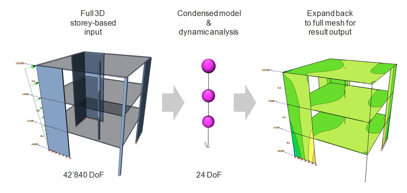
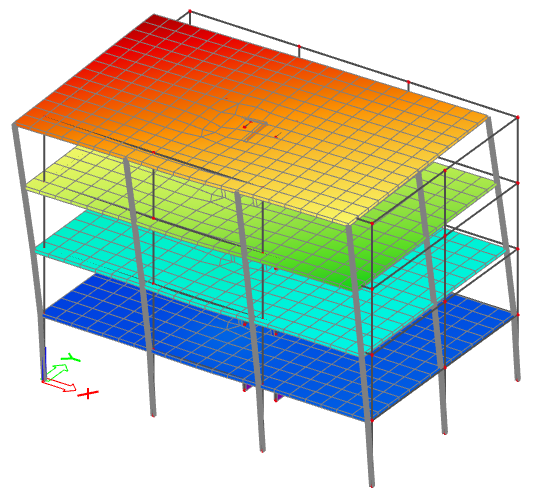
Η SCIA χρησιμοποιώντας βιβλιογραφίες, πρόσθεσε το απλοποιημένο μοντέλο IRS (Improved Reduced System) το οποίο όπως βλέπετε στο πάνω παράδειγμα (εικόνα) μειώνει τους βαθμούς ελευθερίας από 42.840 σε 24!
Το SCIA Engineer χρησιμοποιεί ένα (1) κόμβο ελευθερίας ανά όροφο (R-node) και λαμβάνει υπόψη όχι μόνο το μητρώο δυσκαμψίας (stiffness matrix) του συστήματος, αλλά επίσης και το μητρώο μάζας (mass matrix), κατά τη διάρκεια της διαδικασίας μείωσης.
Αυτή η μέθοδος έχει αποδειχθεί ότι δίνει άριστα αποτελέσματα σε δυναμική ανάλυση ενώ ο χρόνος υπολογισμού μειώνεται δραματικά. Αυτό φυσικά πρέπει εσείς να το επιλέξετε σε μοντέλα δυο ορόφων και άνω και να δημιουργήσετε ορόφους.
Η διαδικασία:
1) Διώροφο μοντέλο (Ισόγειο και 1ος όροφος)
2) Project > Functionality > Dynamics
3) Solver > Dynamics > Use reduced model (IRS)
4) Line grid and storeys > Storeys
Η σεισμική ανάλυση του SCIA Engineer επιτυγχάνεται με βάση την μέθοδο του φάσματος απόκρισης (Response Spectrum) χρησιμοποιώντας την επαλληλία των ιδιομορφών CQC ή SRSS.
- https://www.scia.net/en/support/faq/other-topics/seismic-design-buildings-what-irs
- Reduced Analysis Model
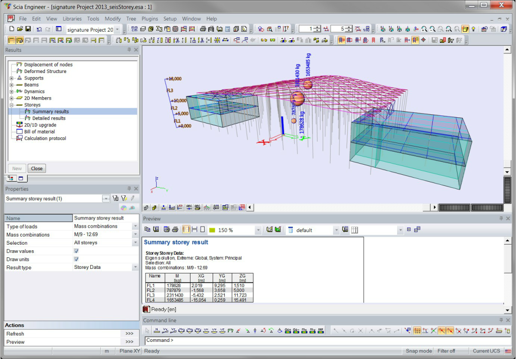
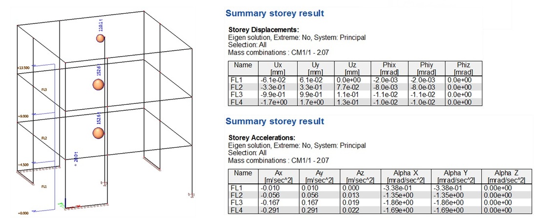
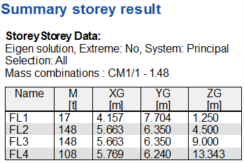
Summary storey results
This service provides results directly produced by the IRS analysis (see previous chapter). At this time, this service is dedicated to result output for the seismic analysis of buildings. It provides single results per storey, such as mass, position of mass center, displacement, acceleration…
Pre-requisites for using Summary Storey Results:
Output Settings The output settings are presented here according to the various types of results that can be obtained from this service. There are 3 types of results:
More: Storey results
Pre-requisites for using Summary Storey Results:
- storeys must be defined (pre-requisite for using the reduced analysis model - IRS)
- the reduced model must be enabled in the solver settings (see chapter 2)
Output Settings The output settings are presented here according to the various types of results that can be obtained from this service. There are 3 types of results:
- Storey Data
- Displacements
- Accelerations
More: Storey results
| Seismic Analysis of Buildings - Storey-related functionality & IRS dynamic analysis.pdf |
| Advanced Professional Training - Dynamics.pdf |
| Seismic Design in Scia Engineer_2013.pdf |
| BM EC8 - Seismic design.pdf |


Περισσότερα
Ισοδύναμη Στατική Ανάλυση (Equivalent Lateral Forces-ELF)
Introduction Seismic ELF analysis is the most well known method for the seismic analysis of structures.
Although it is quite conservative, its simplicity makes it a very popular method for seismic design.
The ELF method is a static analysis method. However, using it in SCIA Engineer requires the input of some data related to dynamic analysis: masses and at least one combination of mass groups must be defined, as the calculation of the seismic equivalent lateral forces is based on the distribution of masses in the structure. The calculation of storey forces is based on the definition of storeys as well as on the reduced system, which must therefore be defined in order to allow using the ELF analysis.
Defining an ELF seismic load case Pre-requisites - before creating an ELF seismic load case:
Then create an ELF seismic load case:
Περισσότερα: Equivalent Lateral Forces (ELF)
Although it is quite conservative, its simplicity makes it a very popular method for seismic design.
The ELF method is a static analysis method. However, using it in SCIA Engineer requires the input of some data related to dynamic analysis: masses and at least one combination of mass groups must be defined, as the calculation of the seismic equivalent lateral forces is based on the distribution of masses in the structure. The calculation of storey forces is based on the definition of storeys as well as on the reduced system, which must therefore be defined in order to allow using the ELF analysis.
Defining an ELF seismic load case Pre-requisites - before creating an ELF seismic load case:
- enable dynamics and seismic analysis in the project settings
- define masses and a combination of mass groups (same as for any dynamic load case)
- define storeys
- enable the reduced model - IRS
Then create an ELF seismic load case:
- create a new load case
- select Action type = Variable
- select Load type = Dynamic
- select Specification = Seismicity
Περισσότερα: Equivalent Lateral Forces (ELF)


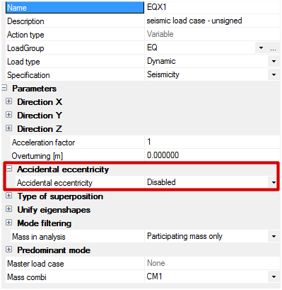
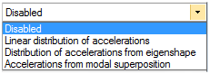
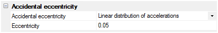
Τυχηματική Εκκεντρότητα (Accidental Eccentricity)
Οι περισσότεροι από τους σεισμικούς κώδικες απαιτούν ότι οι δομές έχουν ελεγχθεί για στρέψη λόγω της μάζας εκκεντρότητας που περιλαμβάνει μια επιπλέον εκκεντρότητας - λεγόμενη τυχηματική εκκεντρότητα. Αυτό απαιτείται για να καλύψει τις ανακρίβειες μεταξύ της πραγματικής δομής και μοντελοποίησης, καθώς και το γεγονός ότι οι μάζες που συνδέονται με τα φορτία των υπηρεσιών μπορούν να διαφέρουν κατά τη διάρκεια της κατασκευής.
Δύο τύποι εκκεντρότητας πρέπει να διακρίνονται για την ανάλυση: η δομική εκκεντρότητα και η τυχηματική εκκεντρότητα.
Η δομική εκκεντρότητα είναι η μετατόπιση μεταξύ του κέντρου μάζας και του κέντρου της δυσκαμψίας της κατασκευής. Αποτελεί μέρος της δομής. Σε μια απλοποιημένη σεισμική ανάλυση μέσω 2D μοντέλα, όπου συνήθως οι κατευθύνσεις Χ και Υ αναλύονται χωριστά, η επίπτωση της διαρθρωτικής εκκεντρότητας λαμβάνεται υπόψη από χειροκίνητη διανομή των στρεπτικών επιδράσεις στην δομή.
Ένας πρόσθετος παράγοντας ασφάλειας εφαρμόζεται συνήθως στη διαρθρωτική εκκεντρότητα να καλύψει ανακρίβειες, που οφείλονται σε αυτή την απλουστευμένη μέθοδο.
Όταν χρησιμοποιείται ένα 3D μοντελοποίηση της δομής, η δομική εκκεντρότητα λαμβάνεται αυτόματα υπόψη λόγω του γεγονότος ότι το Χ και Υ συνδέονται και αναλύονται μαζί, επιτρέποντας στρέψης επιδράσεις να εμφανίζονται άμεσα στην ανάλυση, χωρίς να χρειάζεται να προστεθούν χειροκίνητα εκ των υστέρων.
|
|

|

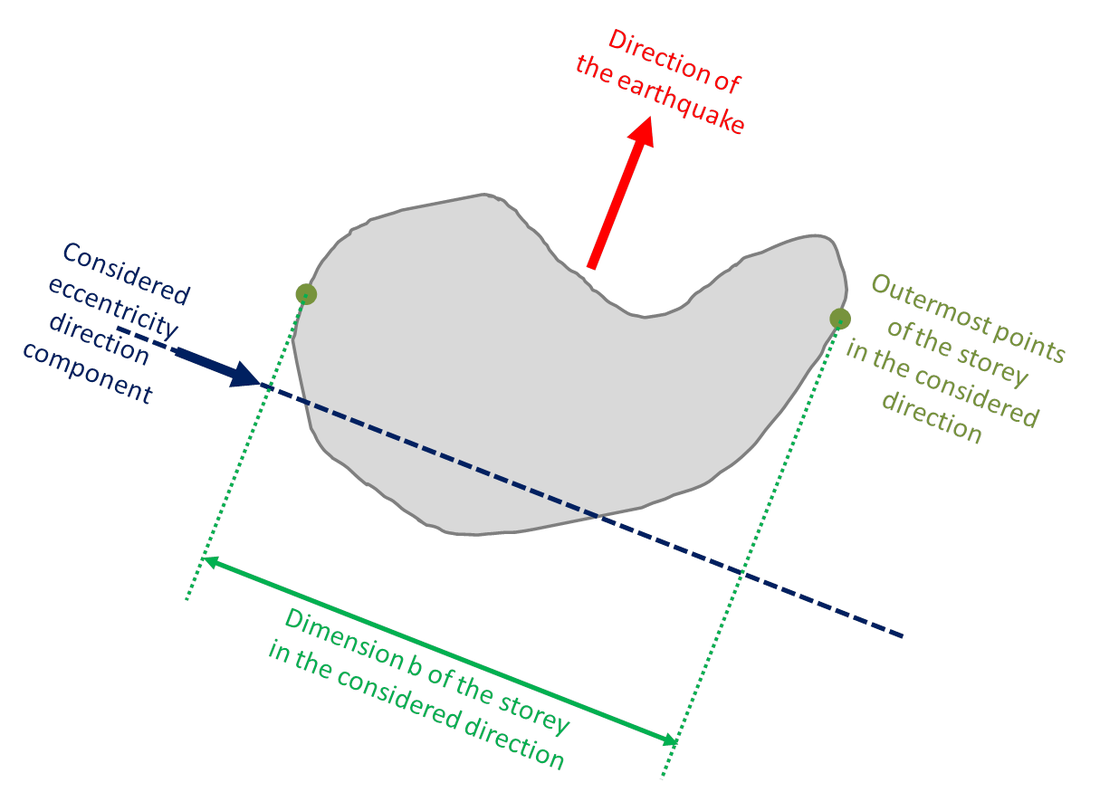
Η τυχηματική εκκεντρότητα αντιπροσωπεύει τις ανακρίβειες στην κατανομή των μαζών στην δομή. Στους κανονισμούς σχεδιασμού συνήθως λαμβάνουν υπόψη ως πρόσθετη μάζα εκκεντρότητας που ορίζεται ως ένα κλάσμα του μεγέθους της δομής.
Στον Ευρωκώδικα 8, η τυχηματική εκκεντρότητα για ένα δεδομένο όροφο, ορίζεται ως 5% του πλάτους του ορόφου κάθετα προς την κατεύθυνση της σεισμικής δράσης.
Σε απλουστευμένες μοντελοποιήσεις όπου η δομική εκκεντρότητα εμφανίζεται ρητά, είναι πολύ απλό να προσθέσετε την τυχηματική εκκεντρότητα στον υπολογισμό. Σε γενικές 3D μοντελοποιήσεις, η δομική εκκεντρότητα δεν εμφανίζεται ως τέτοια και, συνεπώς, είναι πιο δύσκολο να λαφθεί υπόψη για τα αποτελέσματά της σε μια τέτοια περίπτωση.
Στο SCIA Engineer, με τη χρήση του απλοποιημένου μοντέλου IRS σας επιτρέπει την εισαγωγή τυχαίας εκκεντρότητας εύκολα, δεδομένου ότι το απλοποιημένο μοντέλο χρησιμοποιεί μόνο ένα R-κόμβο ανά όροφο.
Η τυχηματική εκκεντρότητα μπορεί να ληφθεί υπόψη είτε ως πραγματική μάζα εκκεντρότητας ή ως πρόσθετες στρεπτικές δράσεις (απλουστευμένη μέθοδος σύμφωνα με τους κώδικες σχεδιασμού).
Περισσότερα: Accidental Eccentricity
Calculate the stiffness center for seismic analysis
In case of a 3D model, the stiffness center is not necessary.
But in case of a 2D model/hand calculation, the stiffness center is needed since the eccentricity is the distance between the mass and stiffness center.
With other words, it is not required for any other check in a 3D model, but it could be interesting to give the user an idea of the design of the building. The explanations in this paragraph refer mainly to the method of equivalent loads for seismic analysis, but some of the exposed principles also apply to a analysis using the response spectrum method.
As explained in the introduction, the structural eccentricity is automatically in a 3D modelization. The location of the stiffness center is taken into account by the fact that the seismic shear walls are modelized in their actual location. Therefore the location of the stiffness center does not need to be known.
In the equivalent load method, the seismic action is usually a concentrated force applied at the mass center of each floor deck. But the location of the mass center does not need to be known either, as applying the horizontal seismic action as a distributed load on the surface of the floor instead of a concentrated force at the mass center will automatically lead to the correct result.
Another advantage of this method is, that if the floor deck may not be considered as a rigid diaphragm, applying the seismic action as a distributed way will result in a more realistic in-plane behavior of the slab.
Hence the location of neither the mass center nor the stiffness center need to be known.
The accidental eccentricity may be represented as follows:

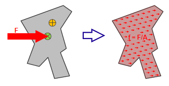
Instead of applying the seismic force at the mass center, it is applied with an additional eccentricity eA.
This can expressed as a force plus a moment applied at the mass center. Going one step further, the force can be applied as a distributed load on the entire surface of the slab, as previously.
The moment can be expressed as a couple of concentrated forces, applied in opposite directions at each end of the slab.
Ultimately, it is again not needed to know the location of the mass center.
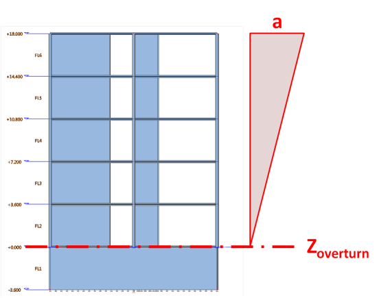
P-Δ Effects και Overturning Moment
Επιλέγοντας το '' Results > Summary Results'' μπορούμε να δούμε και το ''Interstory Drift'' ανά όροφο.
Πρέπει όμως πρώτα να επιλέξετε το ''IRS (Used reduced model)'' όπως γράψαμε στην πιο πάνω διαδικασία, για να εμφανίστεί το ''Summary Results''.
Επιλέγοντας το '' Results > Summary Results'' μπορούμε να δούμε και το ''Interstory Drift'' ανά όροφο.
Πρέπει όμως πρώτα να επιλέξετε το ''IRS (Used reduced model)'' όπως γράψαμε στην πιο πάνω διαδικασία, για να εμφανίστεί το ''Summary Results''.


|

|
|
Εικόνα από το SCIA Engineer (κάτω) μας δείχνει πως βρίσκουμε τις σεισμικές φορτίσεις Fx, Fy, Fz.

Calculation protocol - Base Shears for each mode (Fx, Fy, Fz) - Overturning moment (Mx, My, Mz)
Επίσης οι λεπτομέρειες, ''Overturning Moment'' (Mx, My, Mz) για τους σεισμικούς υπολογισμούς βρίσκονται στο
''Results > Calculation Protocol", αφού γίνει ο σεισμικός υπολογισμός, για γραμμικό υπολογισμό (Linear Calculation).
- Base Shears για κάθε mode και κατεύθυνση (Fx, Fy)
- Overturning moment (Mx, My)
- Spectral accelerations (Sax, Say and Saz)
- G(j) είναι ο συντελεστής (coefficient) του mode για το mode j
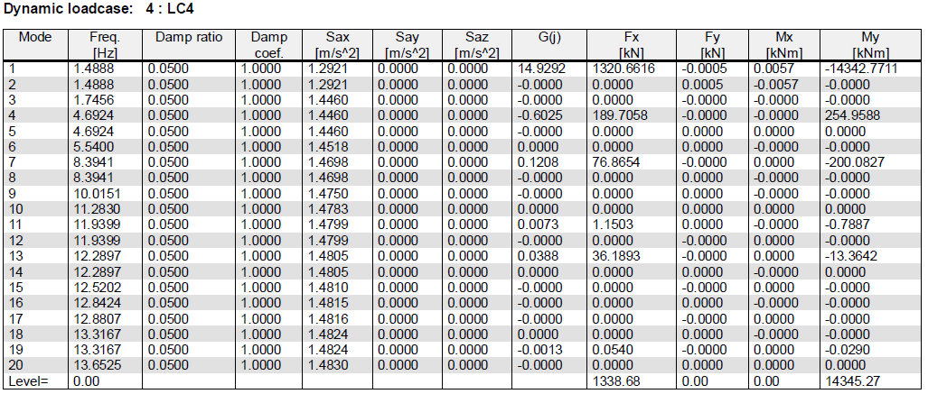
Calculation protocol - Base Shears for each mode (Fx, Fy) - Overturning moment (Mx, My) - Spectral accelerations (Sax, Say and Saz)
Σεισμικοί συνδυασμοί σύμφωνα με τον κανόνα του 30%!
Τώρα δεν χρειάζεται να γράφετε όλους τους συνδυασμούς γιατί πλέον λαμβάνονται αυτόματα υπόψη, σύμφωνα με τον
''EN 1998-1, §4.3.3.5.2 Vertical component of the seismic action''.
Περισσότερα: Load enhancements in SCIA Engineer 14
Τώρα δεν χρειάζεται να γράφετε όλους τους συνδυασμούς γιατί πλέον λαμβάνονται αυτόματα υπόψη, σύμφωνα με τον
''EN 1998-1, §4.3.3.5.2 Vertical component of the seismic action''.
Περισσότερα: Load enhancements in SCIA Engineer 14

Πως ξέρω αν το κτίριο μου είναι στρεπτικά εύκαμπτο (Torsionally Flexible);
Notes about relative modal masses in the context of seismic analysis
A brief analysis of the values listed in the table of relative modal masses can provide quickly a good overview of the seismic behaviour of a building. Several examples are presented below, starting with a typical, sound seismic behaviour. A few examples of less desirable behaviours are illustrated as well.
- Typical regular structure
- Torsional mode in first position
- Significant torsional component in fundamental modes
Περισσότερα στο SCIA Help:
Regular system
This is a typical regular system, almost academic. The obtained results are what is typically expected for a well designed building.
The corresponding mode shapes are shown below:
This is a typical regular system, almost academic. The obtained results are what is typically expected for a well designed building.
- the first two modes exhibit a high relative modal mass in direction X and Y and little or zero in rotation around the Z-axis
- in higher frequencies (here in position 3), there is one or more modes with high torsional participation
- in higher frequencies (here in position 4), there is one of more modes with high vertical participation
- the sum of relative modal masses in direction X and Y reaches 90% with a reasonable number of modes; for the vertical component, it is not uncommon that a larger number of modes is required to reach 90%, however, it is often not necessary to consider the vertical component in the modal analysis (a static equivalent approach is often sufficient)
The corresponding mode shapes are shown below:


Weak system in torsion
The presence of a purely torsional mode at the top of the list is the sign of a shear wall system with low eccentricity, but also an insufficient torsional stiffness. It means, that accidental eccentricity effects could have a serious impact on the structure.
In this case, the shear resisting system is made of a single core in the middle of the building.
From the relative modal mass values, the first two modes are clearly pure torsional modes, as only the Wzi_R component shows significant values. The 4-th mode is less obvious, but the mode shapes of the first 4 modes clearly show pure torsional behaviour, with 1st, 2nd, 3rd and 4th order torsional modes.
Modes 5 and 6 show an interesting discrepancy. As the geometry of the building has a symmetry plane in the Y direction, and the U-shaped core is almost centred, the fundamental translational modes would be expected in direction X and Y. Modes 5 and 6 would be expected to have a high value of relative modal mass in the X (resp. Y) direction and zero in the perpendicular direction, which is not the case. Because the stiffness of the core is almost the same in X and Y directions, the slight irregularity of the mesh near the core (visible on the provided pictures) causes the principal axes of the system to rotate by almost 45°, leading to 2 modes with coupled behaviour in directions X and Y.


Eccentric shear wall system
In case of a shear resisting system with strong eccentricity, modes with combined significant participation in both translation directions and torsion appear simultaneously.
In this case, the first mode has a significant modal mass in direction Y, combined with also significant values for direction X and rotation around the Z-axis. That is symptomatic of a strong asymmetry of the structure and eccentricity of the shear wall system. The mode shape clearly shows the combined translation and rotations components.
The second mode has non-zero but fairly low values for all translational and torsional components. It is a typical second order mode, where positive and negative values compensate each other.
The third mode has again significant values for both translational components X and Y, but a lower torsional component than mode 1. Given the geometry of the structure, it is the logical secondary fundamental mode, roughly orthogonal to mode 1.


